Paper Review: 1Pipe
1Pipe: Scalable Total Order Communication in Data Center Networks Bojie Li, Gefei Zuo, Wei Bai, and Lintao Zhang, SIGCOMM 2021.
This is a fun little distributed systems paper with a novel protocol for data consistency, which only works in cutting-edge data centers. Here’s the gist:
- 1Pipe provides causal consistency and total ordering. (Thus sequential consistency?) Its latency is much lower than most protocols with these guarantees, measuring in tens of microseconds.
- It metaphorically provides “one pipe” that connects all senders to all receivers, with FIFO semantics. Every message is pushed into the front of the pipe and popped from the back. Of course, if the system really worked this way it couldn’t scale. The magic trick is to provide the illusion of a global FIFO, on a many-to-many substrate.
- Nodes can send a one-to-many transmission called a “scattering”: as in a multicast, all messages in a scattering share one position in the total order, but they can have different contents and recipients. A scattering is delivered atomically, i.e. all-or-nothing.
- 1Pipe offers two variants: You can choose the “best effort” or the “reliable” protocol.
Limitations #
When I had read this much of the paper, I was suspicious. Atomic multicast and total order are consensus problems, and consensus algorithms can’t be this cheap. Where’s the rub? Well, 1Pipe is not an Internet protocol. It only works within cutting-edge data center networks:
- All nodes’ clocks must be very tightly synchronized (within roughly a microsecond) for performance, though not for correctness.
- All switches and other nodes must implement the 1Pipe protocol logic.
- The network topology must be a DAG between any pair of nodes (no loops, unlike the Internet).
According to the paper, data center networks are typically “multi-root tree topologies”. The following diagram from the paper is kind of confusing. Imagine that you split every node into two: the sender and the receiver. Place the sender half on the left, the receiver on the right. Then all traffic only goes left to right, and the network is a DAG.
Multi-Root Tree Topology
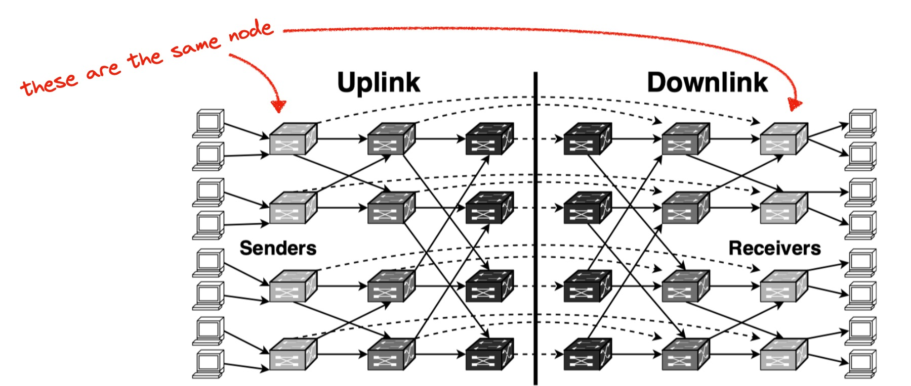
Figure 3: Routing topology of a typical data center network. Each physical switch is split into two logical switches, one for uplink and one for downlink. Dashed virtual link between corresponding uplink and downlink switch indicates “loopback” traffic from a lower-layer switch or host to another one.
Multi-Root Tree Topology
The diagram below, from a 2008 paper, seems clearer to me. It’s obviously tree-like. A message from one node to another must travel up the tree until it finds a common parent, then it can travel down. There are multiple paths between some pairs, since there are multiple roots to choose among, but there are no loops. Somehow this is different from the public Internet, and it makes the 1Pipe protocol safe, though I don’t understand the details.
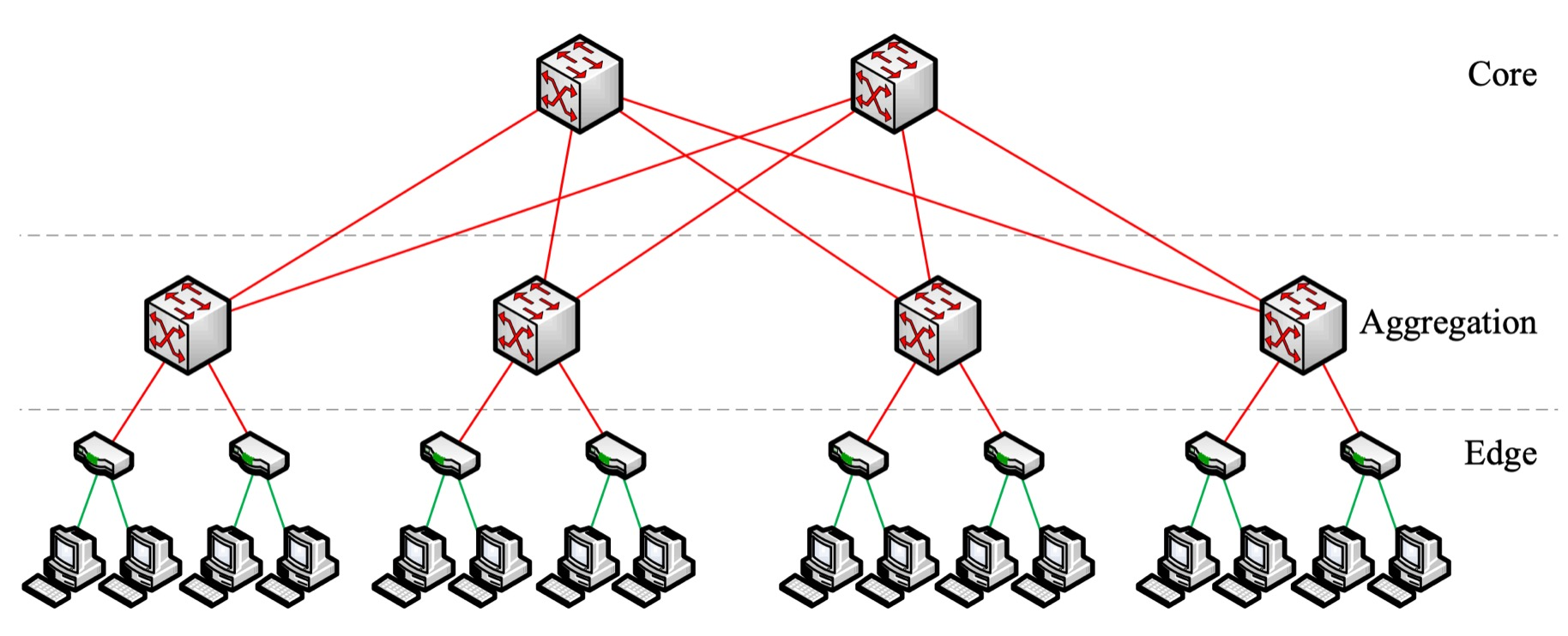
Credit: “A Scalable, Commodity Data Center Network Architecture”, Al-Fares, Loukissas, Vahdat 2008
1Pipe protocol by example #
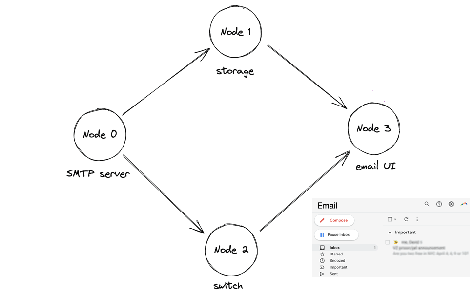
I’ll describe the 1Pipe protocol with a scenario. This is like a scenario in the paper, but I added one node and I’m inventing some details. I found this helpful for understanding. Let’s say there’s an email system with 4 nodes:
- An SMTP server that receives emails.
- A storage node; it receives emails from the SMTP server.
- A switch; it forwards messages from the SMTP server to the UI server.
- A UI server that presents a website like GMail.
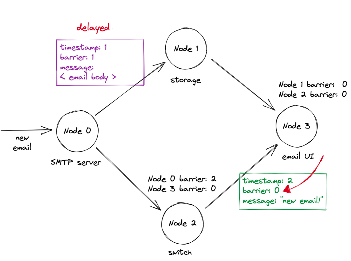
(This is all my invention, not the authors’.) An email arrives, the SMTP server stores it in the storage node. It concurrently sends a notification, via the switch, to the UI server. The UI server requests the email contents from the storage node, and when it receives the contents, it updates the UI:
In the animation above, the UI server requests the email contents after they’ve been stored on the storage node, which is fine. The danger is the UI server might request the contents before the storage node receives them, which would violate causality. Let’s see how 1Pipe ensures causal consistency in that scenario.
First, an email arrives at the SMTP server. The SMTP server sends an “email contents” message to the storage node, then a “notification” message to the switch. In the 1Pipe protocol, all messages include a timestamp and a “barrier” value; initially these are set to the originating server’s clock. So the email contents message has timestamp and barrier 1, and the notification has timestamp and barrier 2. Warning: the first message is delayed!
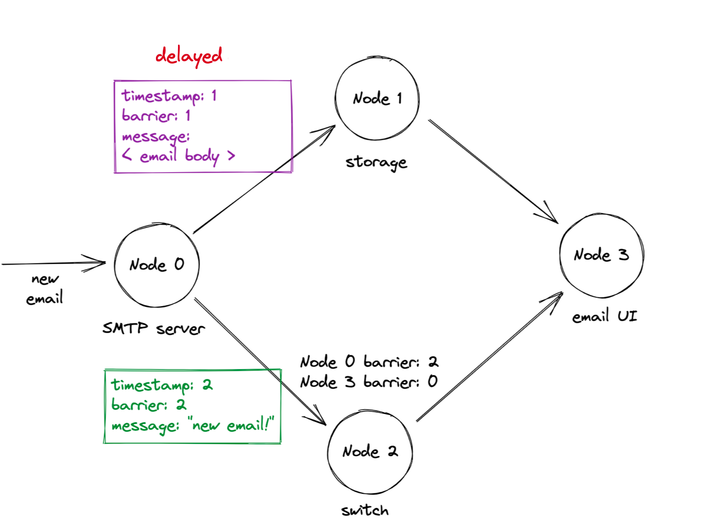
The switch receives the notification with timestamp and barrier 2. Here’s where 1Pipe gets interesting: the switch remembers the last “barrier” value it got on each network link. All nodes promise to send messages with increasing barriers, so the switch knows the SMTP server’s messages will have barriers greater than 2 from now on. The switch wants to tell the UI server what barriers to expect from the switch. Can the switch promise to send barriers over 2? No, because it might still receive lower-barrier messages on its other inbound link. Thus outgoing messages from the switch have barrier value 0: that’s all the switch can promise. In general, a node’s overall barrier is the minimum of its barriers on each inbound link. (We’ll see in a moment how 1Pipe uses barriers to enforce causal consistency.)
When the UI server gets the “new email” notification, it requests the email contents from the storage node. Danger! The storage node still hasn’t received the email contents, so if it processes the UI server’s request now, it will violate causality.
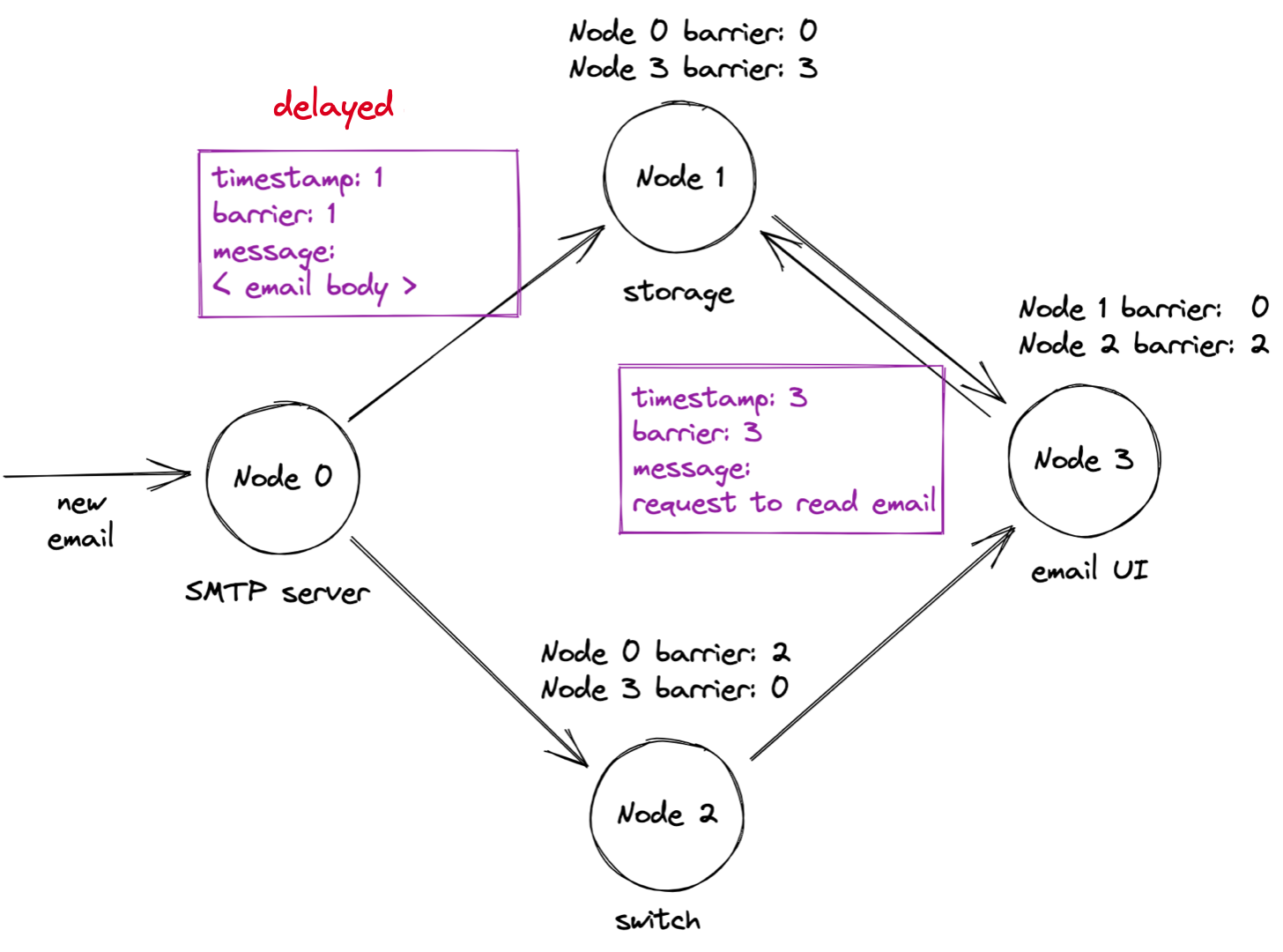
Not a problem, though: the storage node’s overall barrier is still zero, the minimum of the barriers on each inbound link. A node refuses to process any message with a timestamp greater than the node’s overall barrier, so the storage node doesn’t process the request yet.
Now, the old message with the mail contents is finally delivered, and the storage node stores the email contents:
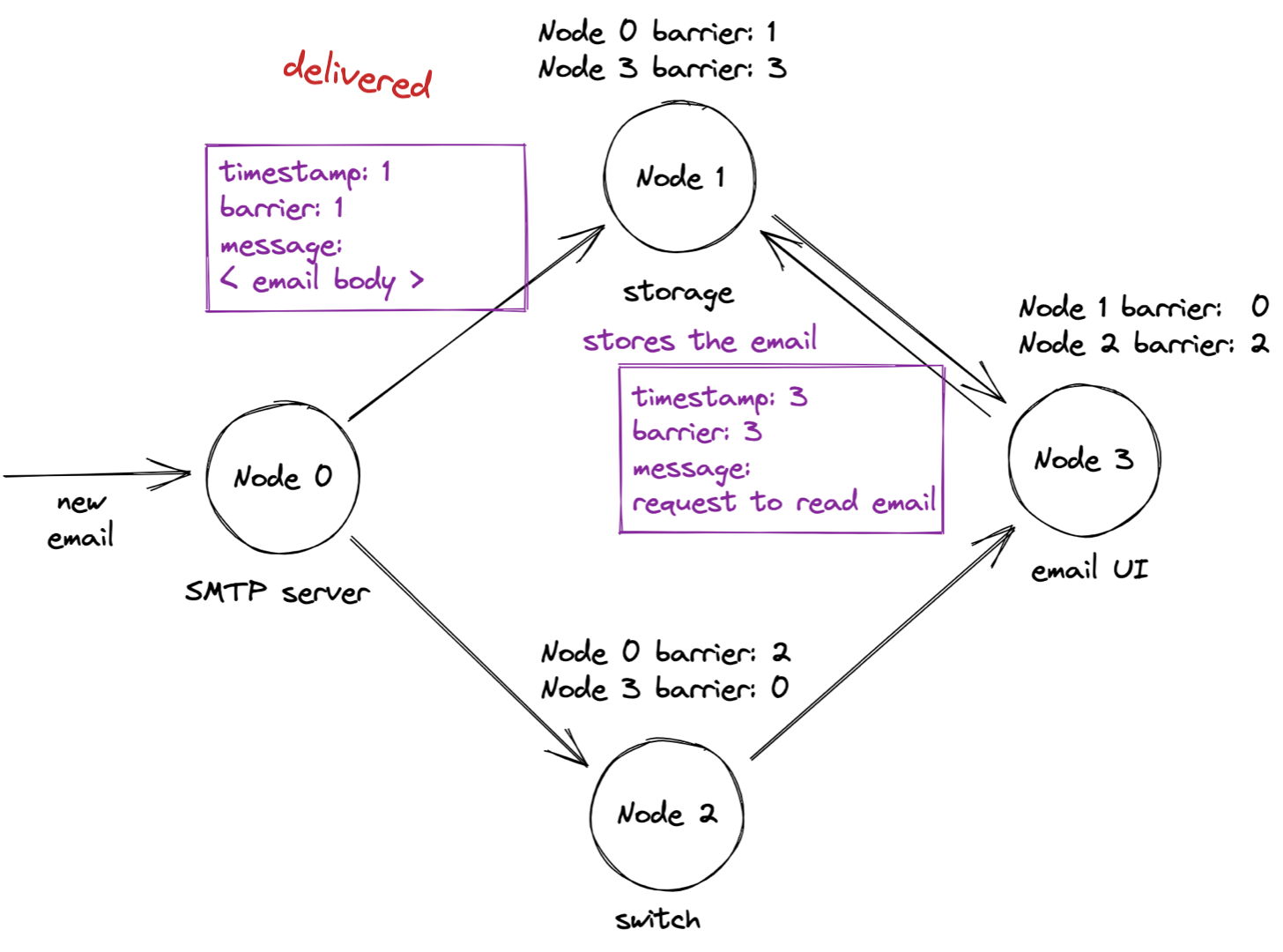
Can the storage node process the timestamp 3 request yet? No, because the storage node’s overall barrier has only advanced to 1. When will it ever advance to 3? 1Pipe has a solution for this problem: “beacon” messages that nodes send periodically over idle links.
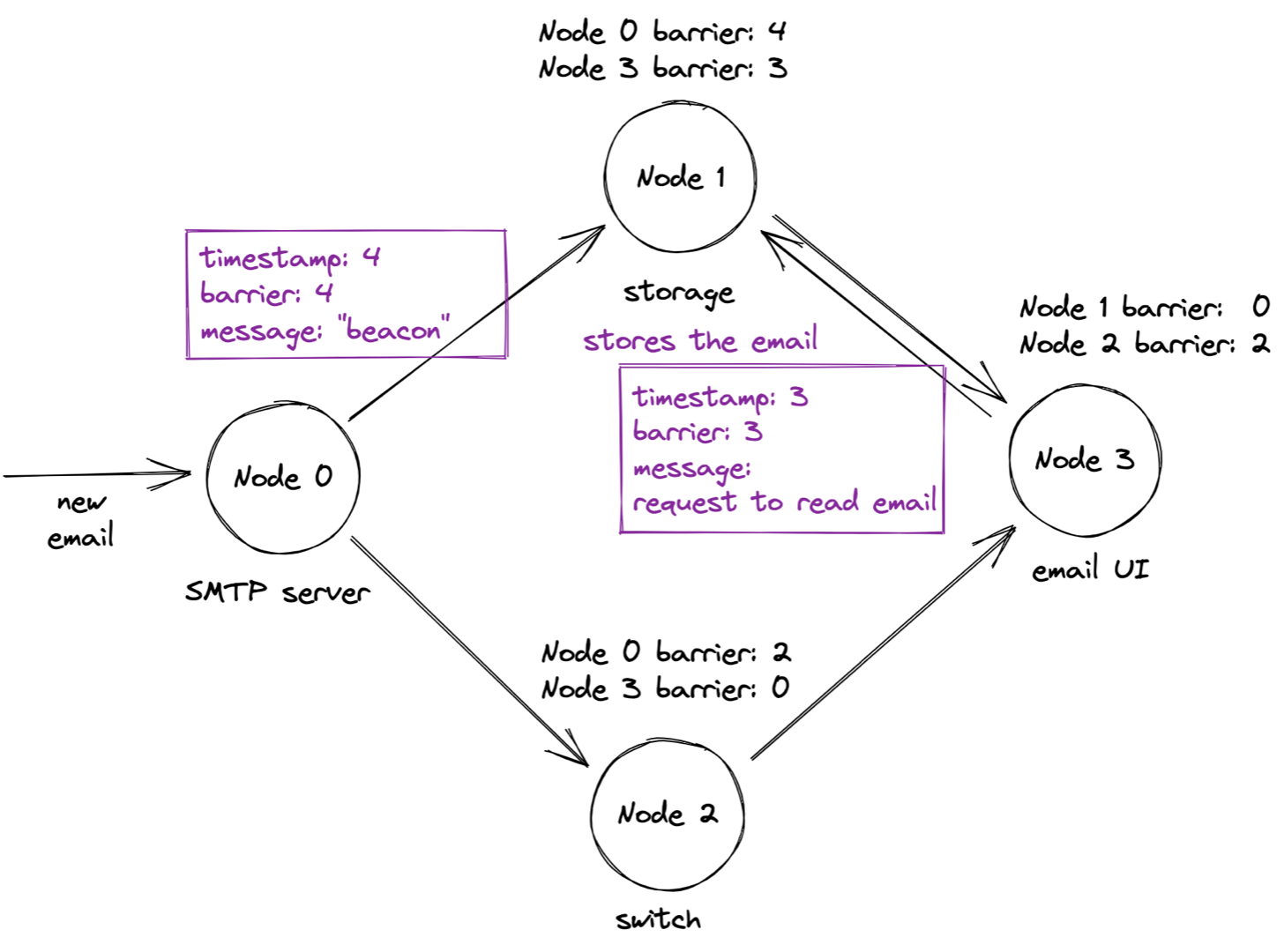
When the SMTP server sends a beacon with barrier 4, the storage node advances its overall barrier to 3. That permits it to process the request with timestamp 3, and respond.
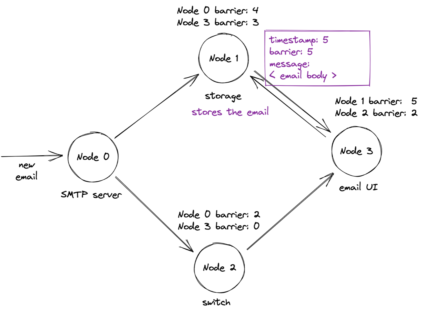
You can see how barriers enforce causality: the storage node waited to process the request until it was certain it had received all older messages on all links. It remembered the last barrier value on each link in order to determine this.
The switch can’t hold messages while waiting for its overall barrier to advance (a switch doesn’t have much RAM), so it updates outbound messages’ barriers to the switch’s overall barrier before forwarding the message. Thus, each message’s barrier value reflects the minimum barrier along the whole path it took. This value tells the destination node that no lower-barrier messages will ever arrive on the same link.
Reliability #
1Pipe offers two reliability levels. The simple protocol I described above is “Best Effort 1Pipe”: it only requires half a round-trip time, but it has few guarantees if any node crashes. There’s also “Reliable 1Pipe”, which resembles two-phase commit: the sender transmits a “prepare” message and retries until all recipients acknowledge it. The “prepare” message ignores barrier timestamps. Then the sender transmits a “commit” message using Best Effort 1Pipe. If this message is lost, I’m not sure what happens: the paper doesn’t mention any way for the sender to detect the error, much less correct it. And yet this two-phase protocol is described in the “Handling Packet Loss” section so there must be a way….
It’s clearer to me how 1Pipe handles crashed nodes, though also unsatisfying. Surviving nodes use timeouts to detect the crash and inform the application, but it’s the application’s responsibility to recover using a traditional consensus protocol like Paxos or Raft:
In fault tolerant applications, 1Pipe provides a fast path in normal cases, and falls back to the application for customized failure handling. More concretely, an application may use state machine replication to replicate its states, and register
onepipe_proc_fail_callbackwhich invokes a traditional consensus algorithm. Each message is scattered to all replicas. When failure occurs, message delivery is stalled, and 1Pipe invokes the callbacks in all non-fail processes. Restricted failure atomicity ensures that all correct replicas deliver the same sequence of messages. If the correct replicas reach a quorum, the callbacks return, and message delivery is resumed. Otherwise, there are too many failed replicas, and the application can choose between consistency and availability. If it chooses consistency and waits for some replicas to recover, the recovered replicas can deliver the same sequence of messages.
So, 1Pipe doesn’t excuse you from implementing a distributed protocol: it handles the happy path, but you handle recovery.
Recovery would be orders of magnitude slower than normal operation. Whoever deploys 1Pipe should think hard about how the rest of the system will react when 1Pipe stalls for crash recovery, or risk metastable failure. The 1Pipe authors clearly optimized for very reliable data center networks where packet loss, crashes, and clock skew are very rare.
My evaluation #
1Pipe seems far faster than other protocols that achieve similar consistency levels, at the cost of high requirements, and expensive and poorly defined error recovery. It guarantees causal and totally ordered communication, aka “CATOCS”. This be the same as sequential consistency, or perhaps the authors don’t claim sequential consistency because 1Pipe doesn’t guarantee delivery. Anyway, it’s a cool protocol! If you have a high-tech data center network and you need super low latency plus causal consistency, then 1Pipe will fit your niche.